The designs are made in 3D with SolidWorks, integrating many modern technologies such as digital axes, force and torque measurement, weighing, level control and vision systems.
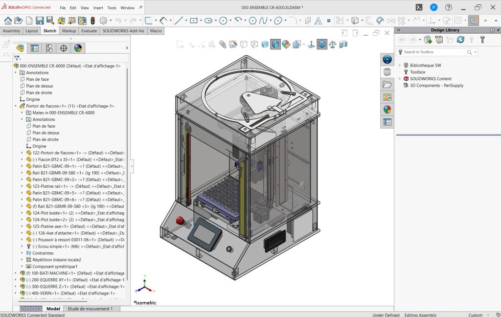
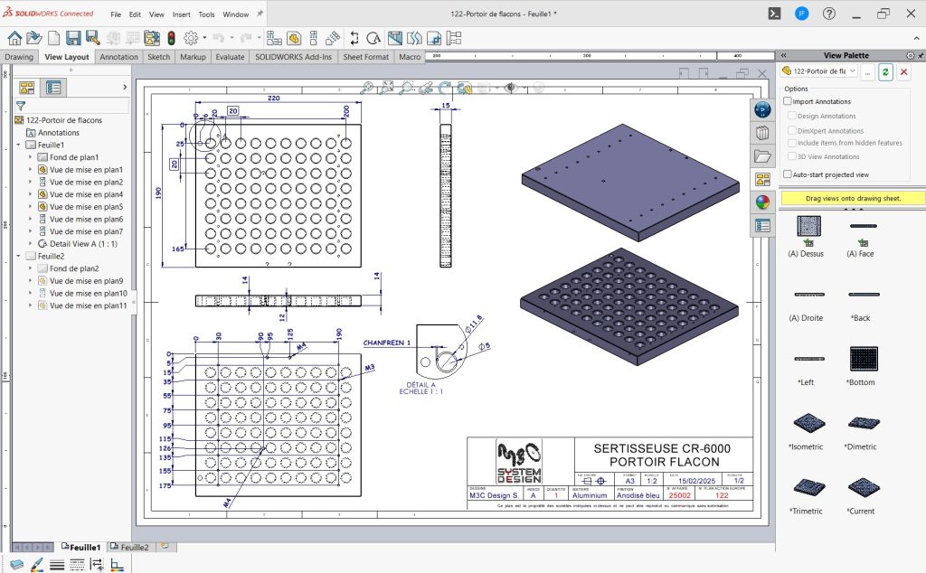
After the design phase, the production drawings and manufacturing files are generated.
With SolidWorks, we can design a wide variety of specialized machines for different industries, ranging from simple mechanisms to complex automated systems. For custom machinery, SolidWorks allows for the creation of:
- Machine Frames and Structures: Frameworks supporting all machine components, including weldments, sheet-metal parts and assemblies.
- Mechanisms and Components: Gears, shafts, actuators, linkages and other functional elements, with motion simulation to validate their interaction.
- Automation Systems: Conveyors, robotic arms and automated handling systems whose movements can be simulated and optimized.
- Custom Tools and Jigs: Purpose-built tooling and fixtures tailored to specific manufacturing or assembly operations.
- Enclosures and Housings: Protective machine casings designed for safety, durability and operation in different environments.
- Electrical Component Integration: Integration of wiring, motors, sensors and other electrical equipment within the machine design.
- Simulation and Analysis: Stress, thermal and motion analyses to validate performance before manufacturing.
- Fluid Systems: Design and analysis of hydraulic and pneumatic systems using SolidWorks Flow Simulation.
In summary, SolidWorks is a powerful tool for designing special-purpose machines by integrating mechanical, electrical and fluid components, simulating their operation and ensuring reliable real-world performance.